This presentation describes the
Hybrid-Electric Vehicle Prototype
and its various systems.
The vehicle is designed following
operating philosophy of a large
Electric Power Grid.
Hybrid-Electric Vehicle Prototype
and its various systems.
The vehicle is designed following
operating philosophy of a large
Electric Power Grid.
 |
| An Alternative Hybrid-Electric Vehicle (A YouTube Video) This is the vehicle's 1st electric run. It was powered by a 3-phase 240/480-volt industrial electric motor, driven by a sinusoidal 3-phase variable frequency, variable voltage inverter, taking its power from a 84-volt battery bank. It may be operated at any frequency range, although I designed the operation of this system for the range 20 Hz to 150 Hz. Since I DESIGNED the inverter myself and BUILT it with the assistance of Mr Edsel Uy of the ECCE Department, and of Mr Sherdon Niño Y. Uy of the Manila Observatory, I could have any DC voltage input, any AC voltage output, and any operating frequency range, as may be desired. I deeply appreciate the assistance that Niño Uy, Mang Cally, Mang Rudy, Mang Numer, Edsel Uy, and Dr Greg Tangonan, so generously gave me. I also want to thank the Ateneo de Manila University, especially its President Fr. Jose Ramon T. Villarin, SJ, the Manila Observatory, the School of Science and Engineering, the ECCE Department, and the Physics Department and their respective Officers and Faculty members for having allowed and encouraged me to conduct this research on their premises. Dean Toby Dayrit, Professors Rosula Reyes, Joseph Nathaniel Libatique and Carlos Oppus provided the academic atmosphere that allowed the students working on the various modules to complete their undergraduate Research Theses successfully. We tested the three Theses for compliance with all the input and output requirements of the overall system specifications. |
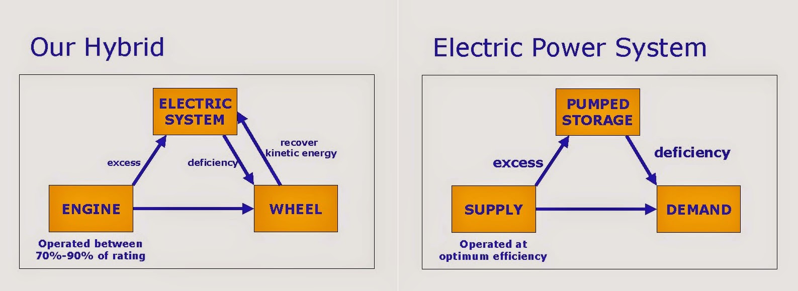
This is a hybrid-electric vehicle prototype. I used my experience managing a large electric power grid, to design this vehicle's propulsion system. This design highlights the synergistic interaction of base-loaded power plants and of grid storage systems, an example of which is a pumped-storage hydro.
If it is operated at all, my engine is ALWAYS operated at its optimum operating range, as base-loaded power plant would be. If the demand on the wheels is light, additional load is added to charge a battery. In an electric grid, this is like pumping water to an elevated lake. The "electric energy" is converted into stored "potential energy."
As the demand gets heavier, charging to the battery is decreased, so that that much more power is delivered to the shaft. As the demand goes beyond the optimum operating point of the engine, additional power is supplied by a tried and tested industrial three-phase induction motor, driven by a variable frequency, variable voltage inverter. Finally, the engine is turned off, when the demand goes lower than its optimum operating point. The electric motor takes over at this point. Note that the electric motor is the "work horse" when the vehicle starts, and when it is about to stop.
This HEV has features that give it a UNIQUE niche.
- I designed it from ground-up, following the principle of operation of an Electric Power Grid, that I managed for a period of four years.
- Its control system is designed to operate with a range of prime-movers, to include diesel-fired engines.
- It is designed to interface with
- RENEWABLES
- Is already "plug-in"
- Already drives industrial machines, like 3-phase electric drills (a video is included in this presentation)
- It is open to the inclusion of a "Co-Generation" system in trucks and buses that would collect waste energy (FREE!) from the engine's exhaust and jacket, in order to provide power to a Lithium-Bromide Absorption Chiller to air-condition the vehicle, or provide heating, as the case maybe. This displaces the need for independent sources for cooling and for heating.
- It uses affordable tried-and-tested and reliable 3-phase 60-Hz induction motors. This approach opens up NEW export markets in developing economies. In this manner, exported vehicles are designed for specific environments, and are more easily maintained.
 |
This HEV uses successful engineering technologies with a view of renewable energy and other energy-efficiency technologies of the future. |
 |
| Our HEV is patterned after the operation of an electric power grid. Electricity is normally delivered to the load (demand). When the demand goes down, we reduce the power output of the power plants that are connected to the grid. These power plants are called regulating plants because they increase or decrease their power output in accordance with the demand on the grid. At some point, these plants will need to be shut down because they are no longer needed. If the load goes even lower, the utility company will need to bring down the power output of the so-called "base-loaded" power plants. These are the large nuclear, coal, geothermal, and oil-fired power plants. By their design, however, they become inefficient and become unstable as their power outputs are reduced. Under this condition of excess power, an electric utility will pump water up to a lake to convert electric energy into potential energy of the water. Now, when the load goes higher than what the regulating plants can provide, water is made to run a hydro-electric power plant to convert the potential energy of the water back into electrical energy. There is, of course, pumping and generation losses. However, these losses are found to be lower than if the utility put up more regulating power plants, and designed their base loaded power plants to have regulating capability. Trivia: The Philippines' Kalayaan Pumped Storage Power Plant is one of the power plants on the electric grid that I managed. The Irish's Electricity Board carved the top of a hill to become an upper lake to pump water into. They also excavated the foot of that hill to become the lower lake, from which to source the water. |
 |
| Our HEV operates in much the same way as an electric power grid, but with an ADDED feature. Whenever we step on the brakes, it recovers the kinetic energy of the vehicle and converts it into electricity. Then it stores this electrical energy in a battery system. The software on the laptop manages this activity. |
The next question that might come to mind would be:
"How do you decide when to run the engine, the generator, the motor, and the charger (brakes)?"
CLICK HERE to view the Guiding Notes of the Coordination Meeting of January 19, 2004. All the hardware and the software must comply, and have complied with each of the boxes on that table. You will see sequential actions and concurrent actions that each of the participating modules perform at every step of the way. Note that thinking has progressed since 2004, and there will be need to update this chart.
Now to continue with the overview of the process. Let us take up the Efficiency Map. This to my mind is the most important chart that an HEV designer must adhere to, very closely. Let us view the chart at this URL:
http://ecomodder.com/wiki/index.php/File:Ford_2.0l_zetec_bsfc.JPG
 |
| Efficiency Map. This Ford engine has an efficient operating range of 1200 to 3000 RPM at a brake torque of 115 to 145 Nm. Within this range, its fuel consumption is about 245 grams per kWh. If we operate the engine at all, it will be operated at this most efficient operating range. If the vehicle requires load outside this operating range, our design requires that we introduce the corresponding load. Our Controller/Dispatcher activates the charger, which acts as a load to bring the operating point back to the most efficient operating range. |
Now for an overview of the milestones.


 |
| This is a theoretical dispatch chart based on our specifications. The control software dispatches the components/modules of the HEV, using this chart.
The engine starts operating only from 70% to 95%, the range that is indicated in the engine's "efficiency map." The electric motor is the SOLE prime-mover outside this range, i.e., from rest to 70% and from 70% down to rest.
The charger presents itself as a "variable load." The engine will be started if the shaft demand is more than the capacity of the motor. This will be about 30% load on the engine. Since we want the engine to be loaded a minimum of 70%, we will need to operate the charger at a level of 40%, to bring the engine to its efficient operating range, as shown in its "efficiency map."
The paragraph, below, gives a description of the dispatch chart
NOTE: For this prototype, the electric motor is rated at about 30% to 40% of the capacity of the engine. In my future design, I will bring the motor capacity much higher than this prototype. The charger and the battery ratings will also need to be increased. Accordingly, my engine's rating will be reduced, enough to overcome the drag at the vehicle's rated speed, with due consideration to headwind.
|
Now the next question is: "What drives the 3-phase, 60-Hz, squirrel-cage induction motor?"
 |
| The prototype uses transformers to step up the 3-phase power to the operating voltage of the induction motor. One would say that this is an inefficient configuration. And that comment is absolutely true. Beyond the prototype, the motor should be driven directly from the battery, through a control switching system, of course. |
We have not yet answered the question. Ok, now we will.
- We start with a battery and have a DC power supply
- You could have any voltage you want
- In our case, we decided upon 84 volts for the prototype, so that we do not unnecessarily expose ourselves to electrocution, i.e., death!
- Now generate a square wave that will go from 0 to 84 volts, stay there for 1 millisecond, then go from 84 to 0 and stay there also for 1 millisecond
- Connect a 10k resistor to the square wave that is generated and connect the other terminal of the resistor to a 1 micro-farad capacitor and measure the voltage on the capacitor
- You will see the voltage to be half of 84, or 42 volts
- Make the square wave stay at 84 and when the voltage on the capacitor hits 62, bring the voltage down to 0
- When the voltage on the capacitor hits 58, switch the resistor back to 84 volts
- When the voltage on the capacitor hits 64, bring the voltage back down to 0
- When the voltage reaches 60 volts, switch it back up
- The first set point is 60 +/- 2 volts, the second is 62 +/- 2 volts
- Make this set point follow a reference sine wave in time and the average voltage at the capacitor will approach a sine wave
- Call this phase A
- Build another set-up like this and make it lag 120 degrees from phase A, and you have phase B
- Build a third set-up and make it lag 240 degrees from phase A, and you have phase C
- NOW, you have built a 3-phase inverter, i.e., converting Direct Current to Alternating current
- An example of clean 3-phase sine waves is given below
 |
| Sine Waves spaced 120 degrees apart characterizes a 3-phase electrical source. Our Inverter builds these sine waves with variable frequencies, but maintaining an electrical distance of 120 degrees. It is able to supply a peak current of 90 amperes at 84 peak volts. This is more than enough power to drive our 3-phase squirrel-cage induction motor. |

We have partially answered the question of "what drives our electric motor?" The answer is an INVERTER that takes its input from a battery and produces a 3-phase power source for the motor.
Ok, we have an inverter. But how does the inverter produce AC from DC?
 |
The process is as follows:
|
This description sounds very easy and straight-forward. And it is. The issues are normally found in the components and their corresponding ratings. In this work, the most critical are their voltage and speed ratings. Current ratings have a significant tolerance, voltage hardly any, and inadequate speed blows up your IGBT's (a term that stands for "insulated gate bipolar transistor").
 |
| Very Important Landmarks |
At this point, let me give three videos, which I recommend that you watch.
- The first one shows the beginnings of the creation of the sine wave at the laboratory
- The second shows the inverter driving a 3-phase electric drill
- The third is my YouTube video of the HEV
Video 1 - The beginnings of the Inverter
This is a video of the early stages of the variable frequency, variable voltage inverter, with current controller. Its output could be a SINUSOIDAL VOLTAGE or it could be a SINUSOIDAL CURRENT. These combined features make it technically ready to synchronize to the Power Grid, WITHOUT sophisticated and expensive synchronizing equipment.
Video 2 - The Inverter drives a 3-phase industrial drill
Many developing countries have capabilities to build their own indigenous vehicles.
Philippines
Vietnam
Thailand
China
Pakistan
India

Video 3 - My YouTube Video
This is a video of the early stages of the variable frequency, variable voltage inverter, with current controller. Its output could be a SINUSOIDAL VOLTAGE or it could be a SINUSOIDAL CURRENT. These combined features make it technically ready to synchronize to the Power Grid, WITHOUT sophisticated and expensive synchronizing equipment.
Video 2 - The Inverter drives a 3-phase industrial drill
This video demonstrates that this HEV's 3-phase inverter drives a 3-phase industrial drill and can also drive irrigation pumps, supply electricity to homes, and to other applications.
This is one very important feature that makes it UNIQUELY attractive to developing countries abroad, where only single-phase power is available, especially in farms and remote areas. You will use the hybrid to transport produce from the fields, such as rice or corn, and bring them to one area where you have a 3-phase electric motor that drives a rice or corn mill. Or you could drive irrigation pumps with your HEV.
Many developing countries have capabilities to build their own indigenous vehicles.
Philippines
Vietnam
Thailand
China
Pakistan
India
(Photo courtesy of Niño Uy, 2005)
This photo shows an irrigation pump that is driven by a single-cylinder diesel engine. Our HEV is able to fulfill the diesel engine's function through a 3-phase induction motor of the same rating. While the HEV is able to fulfill the function, a study will need to be undertaken on each and every condition, in order to confirm that the economics is advantageous.
This photo shows an irrigation pump that is driven by a single-cylinder diesel engine. Our HEV is able to fulfill the diesel engine's function through a 3-phase induction motor of the same rating. While the HEV is able to fulfill the function, a study will need to be undertaken on each and every condition, in order to confirm that the economics is advantageous.
Video 3 - My YouTube Video
This 4.5-minute video walks you through the whole concept behind the technology of this HEV. You will note that this alternative technology is very doable, and produce very affordable products.
How do I control the speed of the motor? There are several ways that are acceptable engineering practices.
In summary, my controller has three set points, with which I control the speed and power of the 3-phase AC motor. They may be manipulated individually, or in sequence, or concurrently/parallel, to achieve the desired effect. These are:
- First Method.
- Run the motor up to synchronous speed (less induction motor "slip")
- Adjust the frequency up or down and the motor will change speed to follow the frequency
- Second Method.
- Impress a reduced voltage on the motor
- Increase the voltage to reduce the "slip" of the motor and it will run faster
- The speed and torque of the motor will change as the voltage is varied
- Third Method.
- This is could be used on single-phase systems
- As the system is running, skip one complete wave, or Period
- Then skip 2, or 3, or 4, and so forth
- When I do this method, I perform ALL the switching at "Zero Crossing"
- Fourth Method. (I perform this on my 3-phase inverter)
- Since I can control the voltage output of my 3-phase inverter (variable-frequency, variable-voltage), I reduce this voltage to ZERO on all three phases
- When I do this, I cut off the magnetism to the rotor, thus removing the prime-moving torque
- At no load, it will coast, and with load, its speed will be reduced faster
- I could maintain the speed of the motor as I bring the voltage output all the way up, and all the way down, depending upon the load requirements
- Now, some care will be exercised, because we do not want to introduce too many transients into the motor that produce harmonics that can generate iron-core heating
In summary, my controller has three set points, with which I control the speed and power of the 3-phase AC motor. They may be manipulated individually, or in sequence, or concurrently/parallel, to achieve the desired effect. These are:
- The amplitude of the reference sine wave - Controls the magnetism and the coupling between the stator and the rotor, resulting in "slip". The reference signal maintains the sinusoidal form of the inverter's output.
- The frequency of the reference sine wave - Controls the speed of the rotating magnetic field at the stator
- The AC current controller - Also controls the magnetism, except that it clips the top portions of the 3-phase sinusoid.
I repeat that one must avoid or minimize the production of harmonics at the iron pieces.
This has been a very serious discussion. Now, let us go to simple trivia.
 |
| This is the first stage of the development of the prototype - the mechanical skeleton. You will see the general purpose engine, that is often used by farmers in rural areas for transport, for powering small boats, and others. Along side the engine is the 3-phase squirrel-cage induction motor. You will also see the pulleys and the belts that produce the required "mechanical advantage". Directly in front of the seat are two levers for changing the vehicle's speed, and a foot-pedal brake. At the handle-bar is a mechanical device that allows the driver to manually adjust the power output of the engine. |
 |
| Fr Jett Villarin, SJ, currently, the President of the Ateneo de Manila University shows his hands-on commitment to innovative approaches to energy. |
 |
| This picture shows the arrangement of the v-belt sheaves. A couple of mechanically interlocked tensioner rollers transfer driving power from one sheave to another to change the mechanical advantage. This is an inexpensive way of building a transmission system for the purpose of the prototype. |
 |
| Visible here are the three major components. On the extreme left is the 3-phase motor. Next to it is the general-purpose gasoline engine. At the extreme right is a second-hand 14-volt 3-phase automotive alternator. We opened this up and took the terminals of one of the coils and connected them to our design of a single-phase alternator with a 90-ampere 10-volt AC primary with a 12-ampere 80 to 120-volt AC secondary. This is the source of the charging current for the 84-volt battery. This scheme has been adopted to be able to demonstrate that the prototype at the shortest possible time and at the least cost. As one can surmise, this secondary can already be connected to the power mains. By design, this HEV is already PLUG-IN. |
 |
| On the picture is Niño (left). He stuck with this research through thick and thin. At right is Mang Cally. He machined, welded, cut and ground any machine element we asked him to. They are standing in front of a dynamometer that was designed specifically for this HEV. It's role is to develop the family of curves for the Efficiency Map. On the left is a weight cradle that applies normal pressure to the pulley attached to the shaft of the engine. The pressure between the surface of the pulley and the pad on the rod will generate a force to pull the rod to our left. The weight on our right counters that force. We have the value of the torque when we multiply this force by the radius of the pulley. Our tachometer measures the RPM. Knowing the torque and the RPM, we are able to compare the "brake horsepower" with the manufacture's rated horsepower, giving us "percent load." We also measure the amount of fuel consumed per unit time. The final quantity that this exercise will yield is "grams per kilowatt-hour." Get grams/kWh for many speeds and for many torques an you have a family of curves, similar to the one shown for the Ford engine.  |
 |
| This is Niño driving the HEV from the Physics Laboratory to its new home, the Manila Observatory. Believe it or not, it is pushed by Mang Cally, at the back, because we did not finish our work on the engine and have not completed the reassembly of our 3-phase inverter. |
 |
| This is a concept of a one-way drive that can be modified to enable more than one shaft to drive only one sheave, or gear as the case maybe. |
 | |
The system's brain, which is the laptop PC receives data from all the modules. It analyses them and sends Control SETPOINTS back to the modules. For example, the charger will operate independently of the PC, while it is plugged into the electric power grid. It will protect itself and the individual batteries as a decentralized stand-alone unit. Similarly, the VFI performs its functions by itself. The PC provides it with SETPOINTS for frequency, voltage, and current. The charger will send a signal to the VFI to shut down when notices that the charge on ANY cell of the battery bank is now low. It does this by pulling down the voltage set-point. This protects this cell from an irreparable deep discharge. |
 | |||||||||||||||
| The charging system follows this control graph. The reference of the design is based on the "DOE HANDBOOK - PRIMER ON LEAD-ACID STORAGE BATTERIES" found in the link below. http://energy.gov/sites/prod/files/2013/06/f2/hdbk1084.pdf |
 |
| This is the charger system of the prototype HEV. The range of the input voltage is 80 to 120 volts AC. |
 |
| This is the voltage and current feedback system. This makes sure that the output voltage and output current are in accordance with the design. |
 |
| This is the control board to interface the computer control software with the rest of the system. It sends control commands to the engine, the inverter, and the charger. It also receives feedback signals that are relevant to the operation of the system. All signals going of the computer to the system pass through an optical isolation system. This prevents transients from entering and damaging the computer. Likewise, signals coming from the system are also opto-isolated from the computer. |
 |
| Charger 01 |
 |
| Charger 02 |
 |
| The system generates voltage transients all the time. These transients will damage the PC, if it gets there by chance. The design incorporates opto-isolators to provide the required electrical isolation, while providing path for the flow of data. |
 |
The control system monitors many points in the Prototype
|